

- Publisher:admin
- Published on:2026-10-27
- Pageviews:8843
When buying cement utility poles, a lot of people get a headache the moment they see that string of letters and numbers on the model code—and end up ordering by gut feeling. The result? Either the load-bearing capacity isn’t enough and cracks show up not long after the line goes into service, or you pay a premium for a specification far beyond what you actually need and waste money on bending capacity you’ll never use. Put simply, the model code of a cement utility pole is a standardized “identity code,” and every character answers one question: where is this pole going to stand, and what does it need to withstand? Read it properly, and you’re more than halfway through selection.
How Do You Actually Read the Model Code? Don’t Let Six Characters Scare You
First, a reminder: the current national standard for annular concrete poles has been updated from GB/T 4623–2014 to GB/T 4623–2025, effective May 1, 2026. The new standard brings real improvements in concrete strength grades and the load system. When purchasing, check first whether the product certificate is issued under the new standard—don’t skip this step.
The unified designation format for national-standard tapered poles is: shape code Z + tip diameter (mm) × pole length (m) × cracking test moment or load code × variety code. Take ZΦ190×12×G×Y as an example. Z means tapered pole; Φ190 is the tip diameter, i.e., the diameter at the top of the pole; 12 means the pole is 12 m long; G is the load class, corresponding to a specific lower limit of cracking test moment; Y means prestressed concrete pole. If G appears alone as the variety code, it means reinforced concrete pole; BY means partially prestressed concrete pole.
The marking logic under the new standard is a bit more rigorous: the cracking test moment is marked directly in kN·m, and the bearing capacity test moment is usually taken as twice the cracking test moment—that’s the pole’s real failure baseline. So looking only at “12 m, 190 pole” is far from enough. The load class and variety code must be locked in together. Otherwise, if the supplier delivers at the lowest level, the line’s safety margin gets quietly shaved away.
Tip Diameter: The First Parameter You Must Lock Down
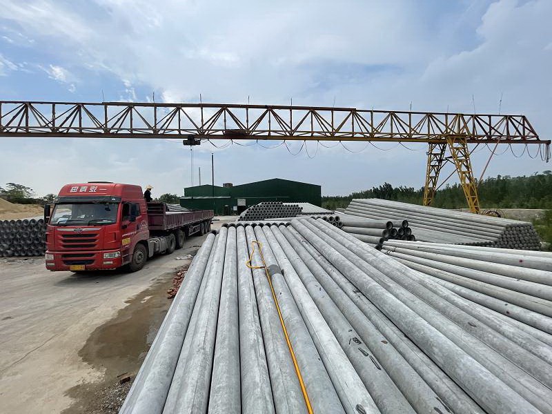
Tip diameter is the “starting diameter” of a tapered pole, and it directly determines the cross-sectional size and bending potential of the whole pole. The taper is usually 1:75; for every 1 m downward, the diameter increases by about 13.3 mm over the tip diameter. A 10 m pole with a 190 mm tip diameter has a root diameter of about 323 mm.
When choosing tip diameter, the key factors are pole length and erection method. For low-voltage lines around 8 m, a 150 mm tip diameter is enough; 10 m poles usually go up to 190 mm; for 15 m and above, 190 mm or 230 mm is common. State Grid typical design recommendations are clearer: single-circuit 10 kV lines are recommended to use Φ190 mm tip diameter; double-circuit lines, because the number of conductors doubles and the load increases significantly, should use Φ230 mm tip diameter. In mountainous areas or terrain-restricted special conditions, a 150 mm pole is not absolutely incapable of replacing a 190 mm pole—but the premise is strict force calculation, not a decision by experience.
Load Class: The Bending “Scale” Behind the Letter
Load class is expressed by uppercase letters; the later the letter, the stronger the bending capacity. Take a pole with 190 mm tip diameter and 15 m length as an example. The national standard includes several levels such as F, G, H, I, and J, with J being the highest. Roughly: Class I corresponds to a standard moment of about 5–10 kN·m, Class J about 10–20 kN·m, Class K about 20–40 kN·m, and Class M enters the 40–80 kN·m range. A 10 kV single-circuit straight pole usually requires no less than Class I; heavy ice areas, long spans, or windy coastal areas should move toward Class K or even M.
Load class isn’t isolated either. It is physically constrained by tip diameter—the load ceiling of a 150 mm pole is far lower than that of a 190 mm pole—and it is also supported by concrete strength: the higher the class, the tougher the requirements on the concrete matrix. The new national standard raises the lower limit of concrete strength for ordinary reinforced concrete poles from C40 to C45; prestressed and partially prestressed poles must be no lower than C50; M-class heavy-duty poles require C50 and C60 respectively. If the strength can’t keep up, no amount of reinforcement can support a high-level bending commitment.
Length and Embedment Depth: The “Lower Half” You Can’t See Decides Success
Pole length is selected according to span and terrain, but embedment depth is the most easily underestimated link in the selection chain. The common industry rule of thumb is: embedment depth no less than 1/6 of pole length plus 0.7 m, and no less than 1.5 m. That means a 10 m pole should be embedded about 1.7 m, and a 12 m pole close to 1.9 m. The cost of insufficient embedment is hidden but fatal: the soil around the pole foundation doesn’t provide enough restraint, and under heavy rain soaking or repeated strong winds, the risk of toppling multiplies. Foundation components such as clamp plates and base plates can’t be omitted either—together with embedment depth, they form the underlying condition for the pole to “stand firm.”
Prestressed, Non-Prestressed, and Partially Prestressed: No “Best,” Only “Most Suitable”
There’s a neat summary in the industry: prestressed poles “would rather snap than bend,” while non-prestressed poles “would rather bend than snap.” Prestressed poles apply compressive stress to the concrete in advance during manufacturing; when external force arrives, it first offsets this pre-compression, so they have high stiffness, small deformation, and strong crack resistance. They suit areas beside roads where vehicles may scrape frequently, windy coastal zones, and scenarios requiring high long-term stable operation. The price is relatively obvious brittleness—once the limit is exceeded, failure comes more suddenly.
Non-prestressed poles are not tensioned; they rely on the natural coordinated action of steel bars and concrete, with better toughness and safety margin. When overloaded, visible fine cracks and bending deformation appear, but as long as the rated load isn’t exceeded, they can keep serving. They cost less, and their corrosion resistance is better suited to saline-alkali land, irrigation districts, and other environments with highly corrosive soil. In 10 kV and below low-voltage distribution networks, the economic advantage of non-prestressed poles is especially prominent.
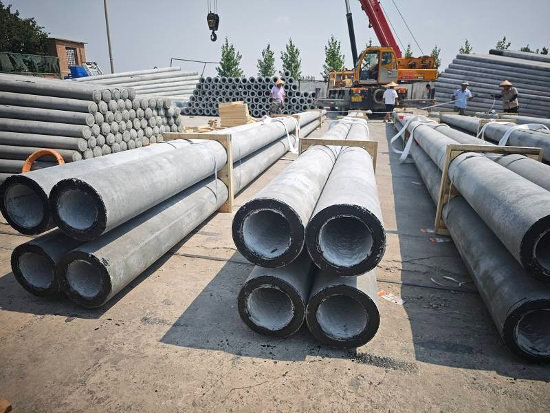
Partially prestressed poles (BY) take a middle route: prestressing tendons ensure crack resistance and stiffness, while non-prestressed reinforcement provides a ductility reserve. They are gradually being promoted in medium- and high-voltage lines and pole positions with complex loading conditions. There’s no absolute ranking among the three; the selection principle is to match the pole’s “character” to the load and environment it will face.
Three Pitfalls That Are Easy to Fall Into—Each Comes at a Cost
Pitfall one: equating “thick” with “strong.” The bending capacity of a pole is jointly determined by pole diameter, wall thickness, reinforcement, and concrete strength. A pole with a 190 mm tip diameter but insufficient reinforcement and low concrete strength can absolutely lose out to a 150 mm pole with solid reinforcement. Thickness only solves the cross-sectional size problem; it doesn’t answer “whether the material can hold up.”
Pitfall two: saving money on concrete strength. The new national standard has already raised the strength threshold, but a few products still use low-strength concrete as a substitute. In windy or corrosive areas, pole bodies with insufficient strength often show surface spalling and steel corrosion within a few years, and maintenance costs far exceed the price difference saved at purchase.
Pitfall three: ignoring the timing of the new national standard. GB/T 4623–2025 has been implemented since May 1, 2026. Checking the standard version on which the certificate is based at the time of purchase is the most direct line of defense for ensuring compliant products.
Choosing a cement utility pole is essentially making a “structural prediction” for the safe operation of a line over the coming decades. Tip diameter sets the volume, load class defines the capacity boundary, variety code matches the stress character, and embedment depth guards the bottom line of standing firm. Read these four dimensions and align them, and the model code is no longer a confusing string of letters and numbers, but a clear and verifiable technical commitment.
Qufu Songli Electric Pole Co., Ltd. has long been engaged in cement utility pole manufacturing. Its products cover various specifications from 7 to 21 m, including prestressed, non-prestressed, and partially prestressed poles, with tip diameters from Φ150 to Φ350 mm. It can also supply high-moment poles, equal-diameter poles, and matching foundation components such as base plates, clamp plates, and anchor plates. Based on centrifugal forming technology and strict implementation of current national standards, the company is committed to providing end-to-end support from model selection to batch delivery for distribution networks and communication lines. Before choosing a pole, it’s worth reading the model code thoroughly; when placing an order, let every bit of investment land where it’s truly needed.
