


- Publisher:mzadmin
- Published on:2026-09-16
- Pageviews:7042
Standard Tip Diameter Series for Concrete Utility Poles
Concrete utility poles may all look similar, but why are some called "150 poles" and others "190 poles"? That number refers to the tip diameter — the diameter at the top of the pole. It is not an arbitrary dimension, but the starting point of the entire pole specification system. The tip diameter determines the pole's "build." The vast majority of circular concrete utility poles are tapered poles with a fixed taper of 1:75, which means that once the tip diameter is determined, a whole series of parameters — including the butt diameter, wall thickness, and weight — are locked in accordingly. For example, for a 10-meter pole with a tip diameter of 190 mm, the butt diameter is approximately 190 + 10000/75 ≈ 323 mm. The larger the tip diameter, the thicker and sturdier the pole body, and the greater its load-bearing capacity.
The tip diameter series specified in the national standard starts at 150 mm and extends upward to cover 170, 190, 230, 270, 310, and up to 510 mm. This series is not arbitrarily defined, but corresponds to the load requirements of transmission lines. The vast majority of low-voltage distribution lines use 150 mm and 190 mm tip diameters, with pole lengths of 6 to 12 meters, bearing the self-weight of conductors and wind loads. For 10 kV lines, the main pole types are concentrated at a tip diameter of 190 mm, while some corner or large-span scenarios may use 270 mm or even 350 mm tip diameters. Only for higher voltage levels or special load-bearing positions are larger tip diameter poles required.
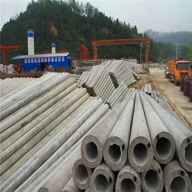
Choosing the tip diameter is essentially choosing "bending resistance." Concrete utility poles often fail not by being crushed, but by being bent and broken by conductor tension or wind loads. The larger the tip diameter, the greater the moment of inertia of the cross-section, and the stronger the ability to resist bending moments. However, an increase in tip diameter also means an increase in weight and cost, as well as greater difficulty in transportation and installation. Therefore, in line design, the selection of tip diameter is a balance between load requirements and construction costs. The naming convention also centers on the tip diameter. The unified national standard format is "tip diameter × pole length × load grade," for example, Φ190×12×39×G, which represents a reinforced concrete tapered pole with a tip diameter of 190 mm, a pole length of 12 meters, and a cracking test bending moment of 39 kN·m. A single number links together the entire technical identity of the pole.
