

- Publisher:mzadmin
- Published on:2026-10-29
- Pageviews:3001
- Source:
Why Are Base Plates and Clamping Plates Configured for Concrete Utility Poles on High-Voltage Lines?
When driving through rural areas or mountainous regions, people often see tall concrete utility poles extending into the distance along high-voltage lines. Above ground, conductors are strung high in the air and the poles stand tall and upright; below ground, however, lies a set of easily overlooked yet crucial stabilization systems. For high-voltage lines, the stability of concrete utility poles is not only related to the operational safety of the lines themselves but also directly affects the safety of nearby personnel and facilities. In the underground portion where the poles are buried, engineers typically install two key components: base plates and clamping plates. One supports the bottom of the pole, and the other embraces the pole shaft, together forming the "stabilizing anchors" of the underground foundation for concrete utility poles.
To understand the necessity of base plates and clamping plates, one must first understand what forces a concrete utility pole bears underground. A high-voltage concrete utility pole can weigh several tons, and together with the weight of fittings, conductors, and insulators, all of this is transmitted to the soil through the bottom of the pole. If the pole bottom directly contacts relatively soft soil, over time it may sink, causing the pole to tilt, changing the sag of conductors, and even creating safety hazards such as insufficient clearance to ground. The role of the base plate is precisely to address this risk. It is usually a prefabricated reinforced concrete square plate with a central groove to support the base of the pole. Its planar dimensions are larger than the diameter of the pole base, thereby distributing the pressure originally concentrated at the pole bottom over a larger soil area. Simply put, the base plate is like putting a pair of "wide-soled shoes" on the utility pole so that it will not sink deeper and deeper into soft ground. In farmlands, paddy fields, or backfilled soil areas, this design for distributing pressure is particularly necessary because the soil bearing capacity in these locations is often insufficient to support the vertical load transmitted by the pole body alone.
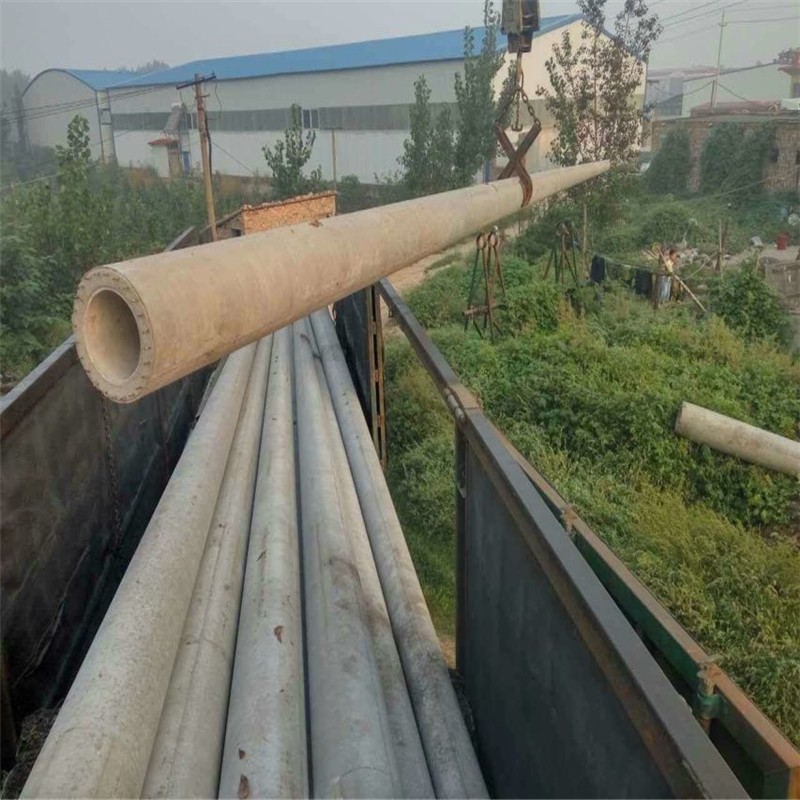
However, utility poles on high-voltage lines do not only bear downward gravity. Horizontal pull generated by wind acting on conductors, unbalanced tension at line corners, and even sudden impacts when conductors break can all create a tendency for the pole body to overturn. At this point, supporting the bottom with a base plate alone is far from enough. The task of the clamping plate is to enhance the pole's ability to resist lateral overturning. Clamping plates are usually U-shaped or arc-shaped, fastened to the lower part of the utility pole with hoop clamps and buried underground at a certain depth, generally at about half the burial depth below the ground surface. When the pole body is subjected to lateral forces and tends to tilt, the side of the clamping plate presses against the surrounding soil, transferring the overturning moment to a larger range of soil mass and thereby creating resistance. Figuratively speaking, the base plate "supports the bottom," while the clamping plate "embraces the waist." For tangent poles, clamping plates are usually buried alternately on both sides of the line; for angle poles or terminal poles, clamping plates are installed on the side in the direction of the force to specifically counteract unbalanced pull. In sections with soft soil or high wind loads, the number of clamping plates may even need to be increased to maintain the upright state of the pole body.
The coordination of base plates and clamping plates reflects the pragmatic principle of "adapting to local conditions and configuring according to need" in power engineering. Not every utility pole must be equipped with both. In areas with good geological conditions, lower pole heights, and smaller loads, the pole's own burial depth and compacted backfill soil may be sufficient to meet stability requirements. However, when lines cross soft geology such as paddy fields, mud ponds, and swamps, or when utility poles are taller, conductor cross-sections are larger, and the wind pressure zone is higher, base plates and clamping plates become indispensable components in the design. Relevant technical materials also clearly point out that base plates are used to reduce the downward pressure borne by the foundation at the bottom of the pole root and prevent the utility pole from sinking; clamping plates are used to increase the overturning resistance of the pole tower and prevent the utility pole from tilting. The two perform their respective duties and are indispensable: with only a base plate and no clamping plate, the pole body may not sink but may be blown askew by the wind; with only a clamping plate and no base plate, the pole body may not easily overturn but may slowly sink into the soil. Only when both are configured together as required by the design can the utility pole obtain complete constraint underground.
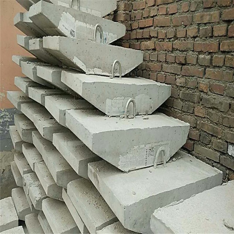
From a construction perspective, base plates and clamping plates are mostly reinforced concrete prefabricated components, installed in sequence after excavating the foundation pit on site, and then backfilled and compacted. The base plate is placed at the bottom of the pit, and the utility pole is positioned on it; the clamping plate is fixed to the specified depth on the pole body with hoop clamps after the pole is erected, and then soil is backfilled in layers and compacted. This process may seem simple, but it has strict requirements for backfill quality. If the backfill soil is not sufficiently compacted and the soil around the clamping plate becomes loose, its anti-overturning effect will be greatly reduced. For this reason, power construction specifications have clear provisions for the burial depth, installation direction, and backfill compactness of clamping plates, ensuring that underground components and soil form a reliable interaction.
Looking back, the configuration of base plates and clamping plates for concrete utility poles on high-voltage lines is essentially solving a mechanical problem: how to make a slender pole stand stably and upright in soft soil. The base plate expands the pressure-bearing area and controls settlement; the clamping plate increases lateral constraint and resists overturning. Together, they tightly "anchor" the utility pole to the earth. For ordinary people who rely on the power grid for electricity every day, these concrete components buried underground and invisible are precisely the silent and solid support behind the lights of countless homes.
